Reverse DC Motor By 2-Channel Simple RF Remote Control System
Reversing motor can be applied to conveyors, awnings, winches; or electrically operated doors, windows, blinds or other mechanicals and appliances. Generally we use motor controller to reverse motor. Easy wire connection makes it easy to operate. But if you just have ordinary wireless remote controls, is it possible to use them to reverse the motor? The answer is yes. Take dc motor for example, today we’ll talk about how it works.
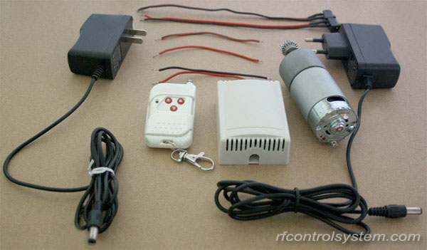
Firstly you need to prepare:
1 x 2 channel receiver in dc12v (latched mode)
1 x 3 buttons transmitter
2 x dc12v power adapters
Some lines
Secondly, see the wiring diagram below, K is normally open terminal; B normally closed terminal and D common terminal. Connect terminal K to the positive and connect terminal B to the negative. Terminal D is supposed to be connected to the motor. In order to avoid interference to motor, power supply for the motor and the relays should be different.
Initial state: terminal B & D are normally closed; terminal D & K are normally open. Terminal D outputs negative power and the motor do not work.
Press button ▲ of transmitter, terminal D & K connected to Relay 1 are closed and terminal D & B are open. At this time terminal D outputs positive power, the motor rotates continuously in the positive direction.
Press button ■ terminal D & B connected to Relay 1 are closed and terminal D & K are open. At this time terminal D outputs negative power, the motor stops to rotate.
Press button ▼, of transmitter, terminal D & K connected to Relay 2 are closed and terminal D & B are open. At this time terminal D outputs positive power, motor rotates continuously in the reverse direction.
Press button ■ terminal D & B connected to Relay 2 are closed and terminal D & K are open. At this time terminal D outputs negative power, the motor stops to rotate.
Go http://www.rfcontrolsystem.com to find all kinds of rf remote controls for light, garage door, gate, motor, etc.


Comments
Post a Comment